In this beginner-friendly video, we discuss the theory and practice of the surface-sensitive technique known as ATR-SEIRAS. We explain the principles of ATR-SEIRAS and provide an overview of the equipment you will need to set up an experiment with a Jackfish cell. We also introduce the four main Jackfish cell types and present several publications that make use of our cells.
Author: admin admin
Video: The Jackfish Cell Family
This video provides a brief overview of the four main spectroelectrochemical cells offered by Jackfish SEC.
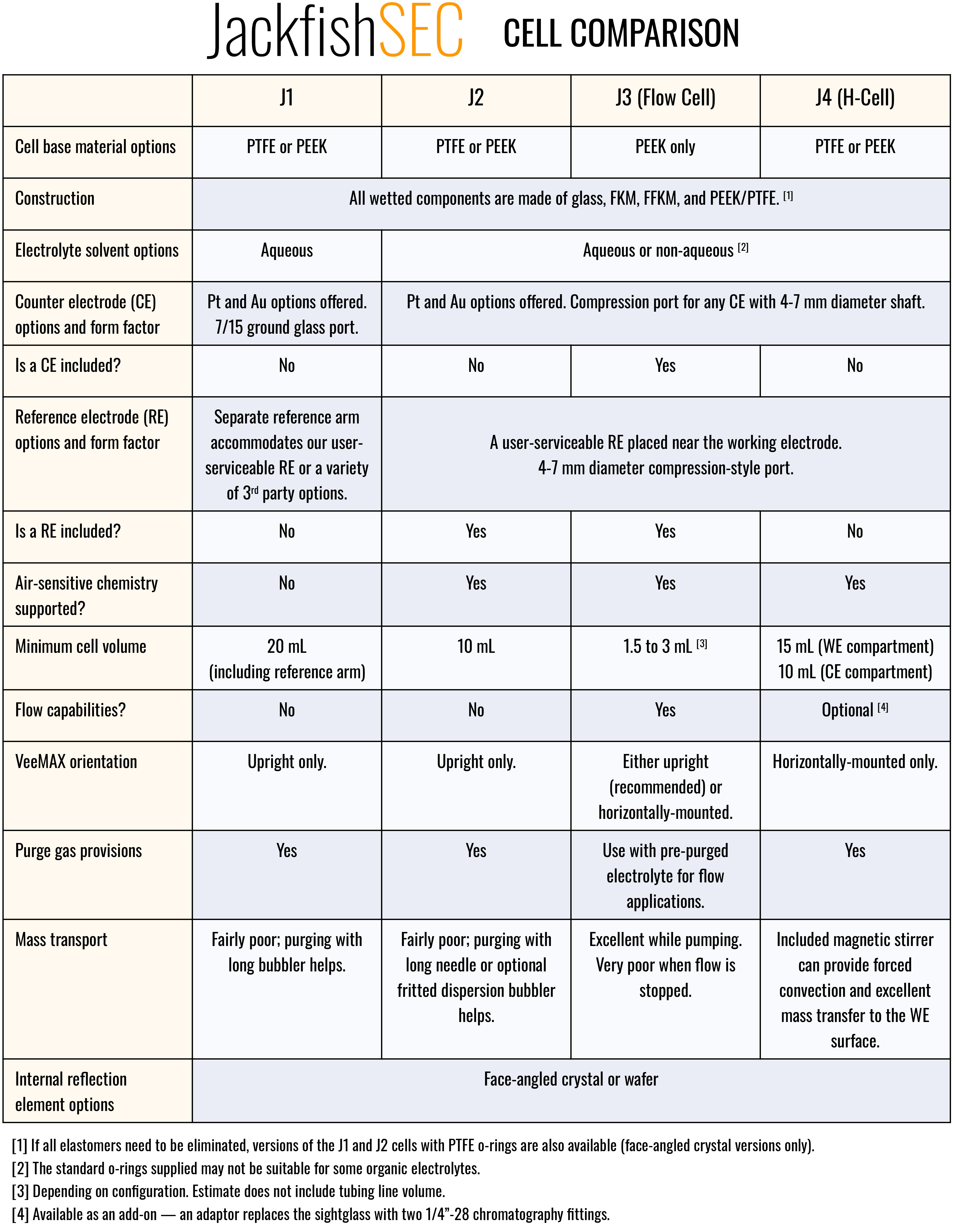
Jackfish Cell Comparison
Having a hard time deciding which Jackfish cell is most suitable for your research? The table below provides a high-level comparison of the four main spectroelectrochemical cells offered by Jackfish.